Rendering Rollout
This page provides information on the Rendering Rollout.
Overview
The rendering rollout is part of the Volumetric Grid Parameters and is located on the Modify panel. The options in this rollout specify how the VRayVolumeGrid effect will be rendered.
Volumetric Options are also available from this rollout for fine-tuning the emissive, diffuse, and opacity properties of the VRayVolumeGrid. Options are divided into three rollouts:
-
Fire Rollout – Controls the emissive (fire) color of the volumetric shader, and the light emitted by the simulator.
-
Smoke Color Rollout – Controls the diffuse color of the volumetric shader.
-
Smoke Opacity Rollout – Controls the transparency part of the volumetric shader.
UI Path
||Select V-Ray Volume Grid|| > Modify panel > Rendering rollout
Rendering
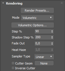
Render Presets... – Specifies a preset from a list of available render presets which might better suit caches from various source software tools.
-
Load from File...
-
Save to File...
-
Fire/Smoke from Phoenix FD
-
Fire/Smoke from FumeFX
-
Fire/Smoke .vdb from Houdini
-
Liquid .vdb from Houdini
-
Fire/Smoke .vdb from Maya Fluids
Mode – Specifies the technique used to visualize the grid content, which can also be considered the render mode for the effect. The first three options are volumetric in nature, while the last three are mesh-based.
Volumetric – Standard volumetric mode similar to VRayEnvironmentFog. This method is used mostly for fire and smoke. As with most volumetric shaders, it is based on the ray marching technique.
Volumetric Geometry – Used mostly to export deep images and render elements such as normals, velocity, etc. It produces the same result as Volumetric mode by using procedural geometry that contains multiple transparent layers.
Approximate and Approximate+Shadows options for the Scattering parameter in the Smoke color window are not supported in Volumetric Geometry mode.
Volumetric Heat Haze – Produces the same result as Volumetric Geometry mode, but enables a heat haze effect to simulate the visual distortion that occurs over hot surfaces (such as pavement in a hot environment). The Heathaze parameter determines the amount of haze. The traced ray changes its direction according to the gradient specified in the Surface section. For more information, see the Heat Haze example below.
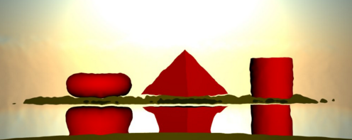
Isosurface – Used mostly for liquids. It produces a V-Ray procedural isosurface geometry using the options in the Surface section.
Mesh – The content is converted into a standard 3ds Max mesh using the Surface section options. This mode is mostly used for liquids.
Ocean Mesh – The content is converted into a mesh, and is extended with an infinite ocean surface. The ocean surface can only be generated when the liquid touches the sides and the bottom of the container. When this option is used, set the Default geometry parameter in the V-Ray System rollout to Static.
The ocean surface can be generated only when the liquid touches the sides and the bottom of the grid, which act as a container for the liquid. The detail of the mesh extension around the simulator depends on the camera resolution - for each pixel of the viewport or the rendered image, one or several polygons are generated, depending on the Ocean Subdivisions option.
Cap Mesh – The content is converted into an open mesh representing only the water surface, suitable for connecting to a user-made ocean surface.
Volumetric Options – Opens the VRayVolumeGrid: Volumetric render settings dialog for fine-tuning the emission of light, diffuse color(s), and opacity of the VRayVolumeGrid.
Step % – Specifies the ray marching step as a percentage of the cell size. As the renderer traces rays through the VRayVolumeGrid, this tells it how often to get information from the grid. If the step is more than 100, some cells will be skipped and artifacts might be produced. When rendering atmospherics with a specific transparency curve, a lower percentage might be needed to preserve fine details. On the other hand, increasing the step increases the rendering speed. This parameter is used with the Volumetric Heat Haze and Isosurface modes. For more information, see the Step % example below.
Shadow Step % – Specifies the ray marching step for shadow rays as a percentage of the cell size. Usually it can be higher than the Step (%), as shadows generally will not need as much detail, and increasing the shadow step will speed up rendering. Increasing the shadow step will improve rendering performance with dome and area lights in particular.
Fade out – Makes the content near the grid's boundaries more transparent in the event that sharp edges are not desired. This parameter controls how far from the boundaries the process should start.
Heathaze – When Render Mode is set to Volumetric Heat Haze, this value acts as a multiplier for the amount of haze. A value of 1 corresponds approximately to the normal heat haze in air caused by the temperature. If smoke or other channel is selected as source, a larger multiplier may be required to achieve a visible result. For more information, see the Heat Haze example below.
Sampler type – Determines how to calculate the values in the points with non-integer coordinates.
Box – Cells are displayed as cubes. There is no blending between neighbor cells. The fastest mode.
Linear – Blends between neighbor cells linearly to smooth out the effect's appearance. Sometimes this option might result in a visible grid-like effect. This type is roughly 20-30% faster than the Spherical type.
Spherical – Uses special weight-based sampling for the smoothest-looking fluid. With increasing resolution, the visual advantage over the Linear method becomes less noticeable.
Cutter Geom – When enabled, rendering will occur only inside the selected geometric object's volume. This parameter is not supported by the Mesh rendering mode yet, but 3ds Max's boolean operators can be used to achieve the same effect. Also, if emissive lights are used, only the ones inside the VRayVolumeGrid gizmo will be rendered.
Inverse Cutter – Rendering will occur only outside of the render gizmo. This is not the same as a gizmo with inverted geometry because any rays that do not intersect the gizmo will be shaded as well.
If using a Cutter Geom for a liquid pouring into a glass or otherwise contained into another refractive object, you may need to set the Mode to Isosurface. By default, the mode is set to Mesh which may produce artifacts in the rendered image.
Example: Step %
This example shows how the Step % value can be used to improve the quality of the ray-marching.
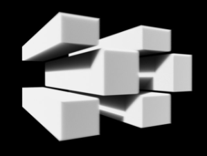
Step %: 50
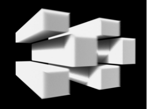
Step %: 150
Example: Heat Haze
Heat haze adds refraction at each ray-marching step through the volume. To turn on heat haze, choose Volumetric Heat Haze as the Render Mode , and set the Heathaze parameter to a value greater than 0.
Heathaze adds refraction at each ray-marching step through the volume. This only affects the camera's view. Heat haze will not affect shadows cast through a volume.
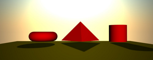
Heat haze: off
Heat haze: on
Surface
This section controls the conversion of the grid content into geometry. When Mode is set to Mesh, Ocean Mesh, Cap Mesh or Isosurface, the Surface channel and appropriate Isosurface level must be set. The technique is based on the isosurface concept which is the 3D version of the isoline, well known from topological maps and weather forecasts.
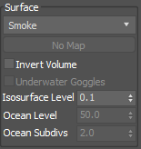
Surface – Controls which physical channel represents the isosurface. By default it is the liquid channel, but smoke or other channels can be rendered as isosurface geometry.
Texture – The values of a custom texture will define the mesh surface.
Temperature – The Liquid/Temperature channel will define the liquid surface. Temperature is typically in the range 0-1 for Liquid simulations and 600-2000 for Fire / Smoke simulations.
Smoke – The Smoke channel will define the liquid surface. Smoke is typically in the range of 0-1 for Fire / Smoke simulations.
Speed – The Speed channel will define the liquid surface. Speed channel output has to be enabled for this to work. Speed is calculated as the length of the velocity vector for each voxel.
Fuel – The Fuel channel will define the liquid surface. Fuel channel output has to be enabled for this to work.
Texture – If the Surface channel is set to Texture, this slot specifies the texture. In Mesh, Ocean Mesh, Cap Mesh and Isosurface render modes, the selected map will completely replace the cache files that have been loaded, if any.
Invert Volume – By default, the values above the surface level are considered internal. When enabled, this option swaps the inside and outside. Note that this should be enabled for OpenVDB level sets.
Underwater Goggles – Available only when Mode is set to Ocean Mesh or Cap Mesh. When enabled, specific corrections are introduced when the camera is placed under the water. The correction just adds a few polygons in front of the camera, thus keeping it outside the mesh. The result is similar to the real underwater goggles, where the field of view is shrunk.
Isosurface Level – The threshold level that determines which cells are considered full/empty. Only cells with values above this level will actually be rendered. The higher the value, the smaller the volume of the isosurface geometry, and vice versa. With higher values, fewer cells will have enough liquid to be visible. Note that for OpenVDB level sets, this should be set to 0.0 to get an accurate result.
Ocean level – When Mode is set to Ocean Mesh or Cap Mesh, this value specifies the level to be considered the water level.
Ocean subdiv. – Available only when Mode is set to Ocean Mesh or Cap Mesh. This value determines how many vertices will be generated for each pixel of the image when generating the far areas of the surface. Like V-Ray subdivisions, the square of the value is used, i.e. if the subdivisions increase twice, the vertex count will be increased four times.
Motion Blur
The parameters in this section affect motion blur for the effect.
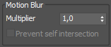
Multiplier – Specifies a multiplier for the motion blur effect. Can be a negative number.
Prevent self intersection – For mesh modes, motion blur is calculated by shifting each vertex toward the velocity by the shutter time. In certain cases the shifted vertex might penetrate the opposite geometry side, causing problems in the rendering. This option is provided to prevent such situations, but it must be used only when the issue is observed, because the self-intersection analysis is expensive.
Mesh Smooth
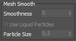
Smoothness – Specifies the number of smoothing passes. Higher values will produce smoother results but require more time to calculate.
Use Liquid Particles – For mesh modes, enables advanced particle-based smoothing of the mesh. Correct use of this option requires Liquid particles to be simulated and exported to the cache files.
Particle Size – Specifies the distance from the mesh to the particle centers, which can be used to make the liquid appear thicker or thinner. This value is available only when Use Liquid Particles is enabled.
Displacement
Displacement is a technique intended to add detail to the simulation during the rendering. The idea of the displacement is similar to geometry displacement, where a texture is sampled and points are shifted in a direction at a distance determined by the texture.
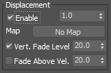
Enable – Enables or disables displacement.
Multiplier – Additional multiplier for the displacement amount.
Velocity based fade out – When enabled, the displacement amount will fade out based on the velocity of the fluid. This means that a slower moving fluid is displaced more than a faster moving fluid.
Fade out zone – Specifies the velocity (in cells per second) at which the displacement amount is set to 0. For velocities between 0 and the value specified in this parameter, the displacement amount is interpolated. Parts of the fluid with velocity higher that the value specified here will not be displaced.
Type – Specifies the displacement technique. This parameter is ignored when Mode is set to Mesh, Ocean Mesh or Cap Mesh. In this case, either Surface driven or Vector displacement is applied depending on whether the displacement map selected for the Map parameter is monochrome (Surface driven) or color (Vector).
Gradient driven – Requires a monochrome texture map. The point is shifted toward the field's gradient by the texture brightness. This method is suitable for smoke and fire. If the default temperature channel is not being displaced, the correct channel must be selected from the Surface list.
Surface driven – Requires a monochrome texture map. The point is shifted by the texture brightness toward the normal of the point's projection on the isosurface. The texture is also sampled at the projection point. This method is slower than the Gradient driven method, but produces better results, similar to displaced geometry. For smoke and fire, the correct channel must be selected from the Surface list.
Vector – Requires a colored vector texture map (with negative and positive values). The point is shifted by the texture color interpreted as 3D vector. This displacement mode is intended to be used with meshes and produces a similar result to standard V-Ray displacement. When compared to Surface driven, the Vector method can can produce more complicated surfaces. For example, a wave texture using this method produces waves that have a convex back side and a concave front side, in contrast with the symmetrical forms produced by Surface driven displacement.
Advection – Requires a colored vector texture map (with negative and positive values). This method is similar to the Vector method but does not produce grainy structures for fire and smoke. For more information, see the Advection and Advection Displacement Maps examples below.
Map – Specifies the displacement map. Depending on the Type parameter, a monochrome map or a color map may be required. If a colored map is passed when a monochrome map is expected, the strength of the displacement is determined by the total intensity of the color. If a monochrome map is passed when a vector map is needed, the entire displacement will point in a single direction. For more information, see the Surface Driven vs. Vector Displacement example below.
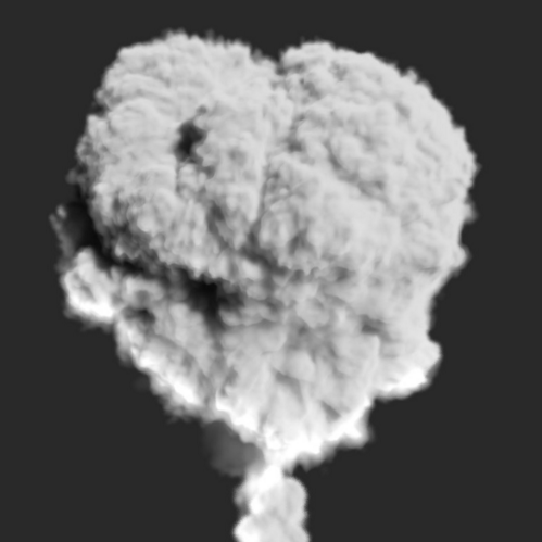
Example: Surface Driven vs. Vector Displacement
Surface driven displacement
Vector displacement
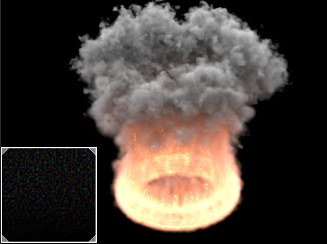
Example: Advection
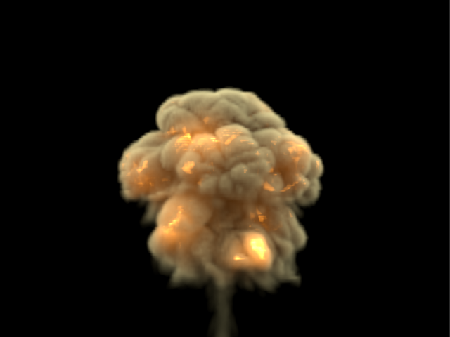
Regular smoke and fire, 5M cells
Advection displacement with the simulation's own velocity,
using a PhoenixFDTexmap and multiplied by a noise map
Example: Advection Displacement Maps
Advection displacement with a vector map between -1 and 1
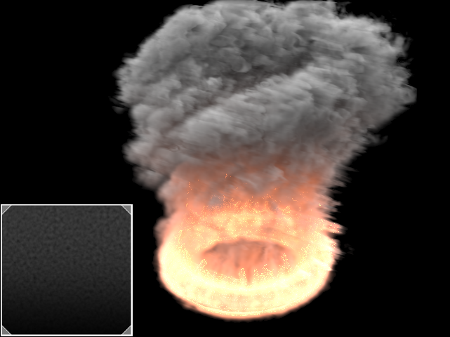
Advection displacement with a monochrome map between 0 and 1
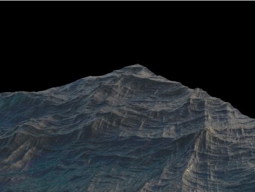
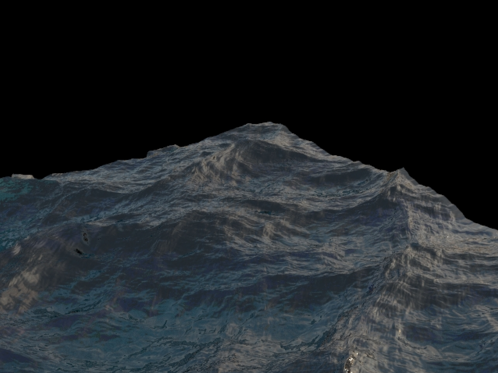
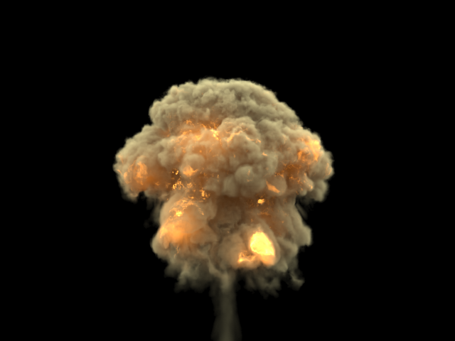
Example: Volumetric Displacement
A grid with 24 million cells with applied displacement. This resolution is not enough by itself for a convincing result.
Enable parameter off for displacement
Enable parameter on for displacement